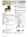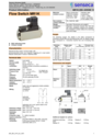
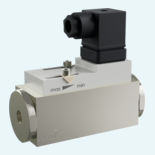
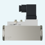
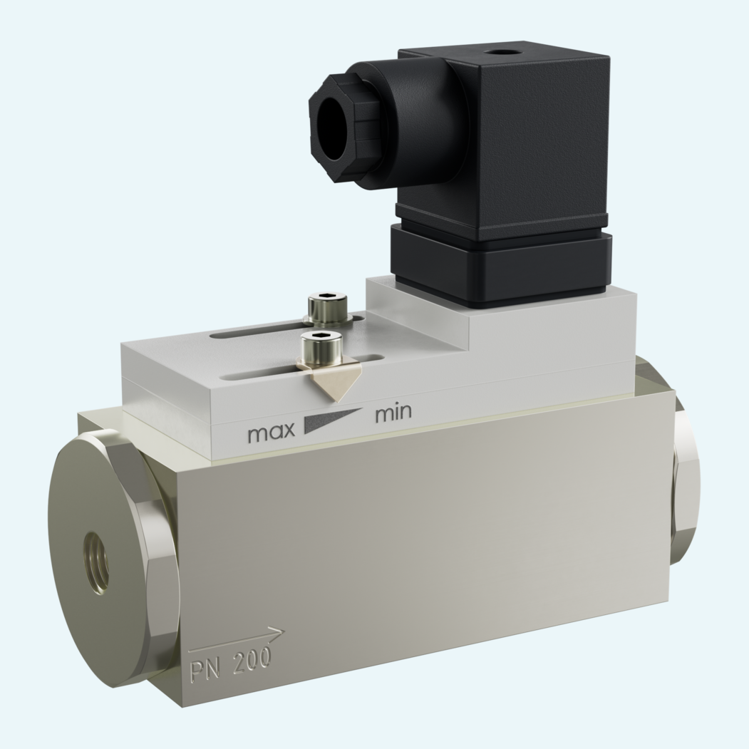
In process lines where flow has to be monitored without unnecessary electronics, a mechanical switching principle keeps operation clear and dependable. The MR1K uses a spring-supported piston with magnetic actuation of a reed switch for liquid or gas media, with H2O switching ranges from 0.4...4 to 6...60 l/min.
The compact body fits DN 8 to DN 25 lines with G 1/4 to G 1 internal threads. Brass and stainless steel versions allow the wetted material selection to match the medium, while optional mechanical indication gives operators a local view of the flow range.
Commissioning remains practical on site. The switch head can be adjusted longitudinally to set the switching value, and options include M12x1 connection, 2.5 m cable, signal lamp in the DIN 43650-A plug, a second switch head, reinforced piston, PN 500 high-pressure brass version and temperature indication from 0...120 °C.

A spring-supported piston moves with the medium flow and magnetically actuates a reed switch. The design is specified for liquid or gas media.
The family can be supplied without mechanical indication or with side-mounted O/O1 indication or frontal J indication, depending on the selected configuration.
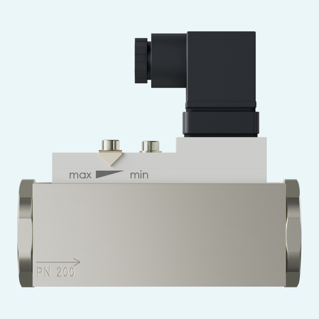
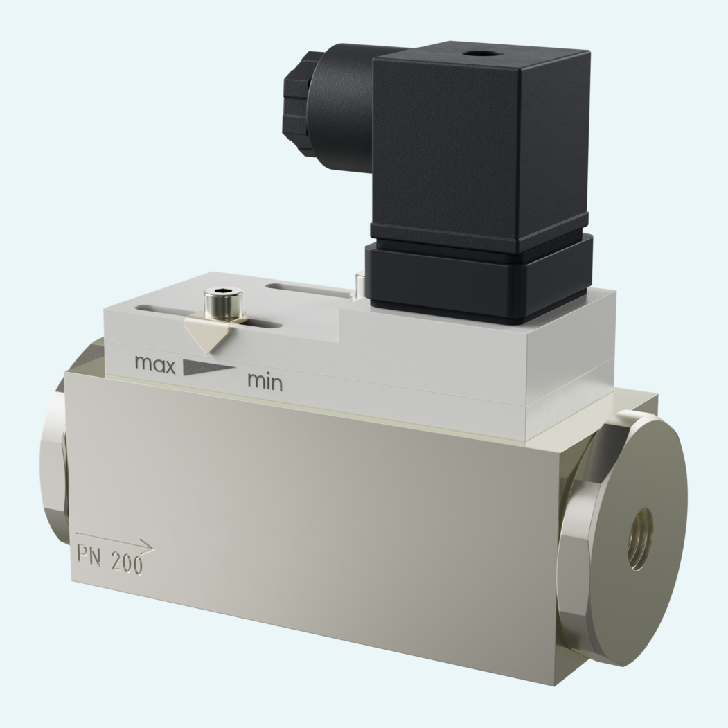
The switch head can be moved longitudinally to set the switching value. Once the switching value is reached, the switching unit is fixed with fastening screws.
Available options include a DIN 43650-A plug with red or red/green signal lamp, M12x1 round connector or 2.5 m cable with cable gland.
The standard installation position is horizontal flow from the left. Other mounting positions are possible, but they influence the switching point or switching range.
Available options include special ranges, special scaling, a 0...120 °C temperature indication and a reinforced piston.