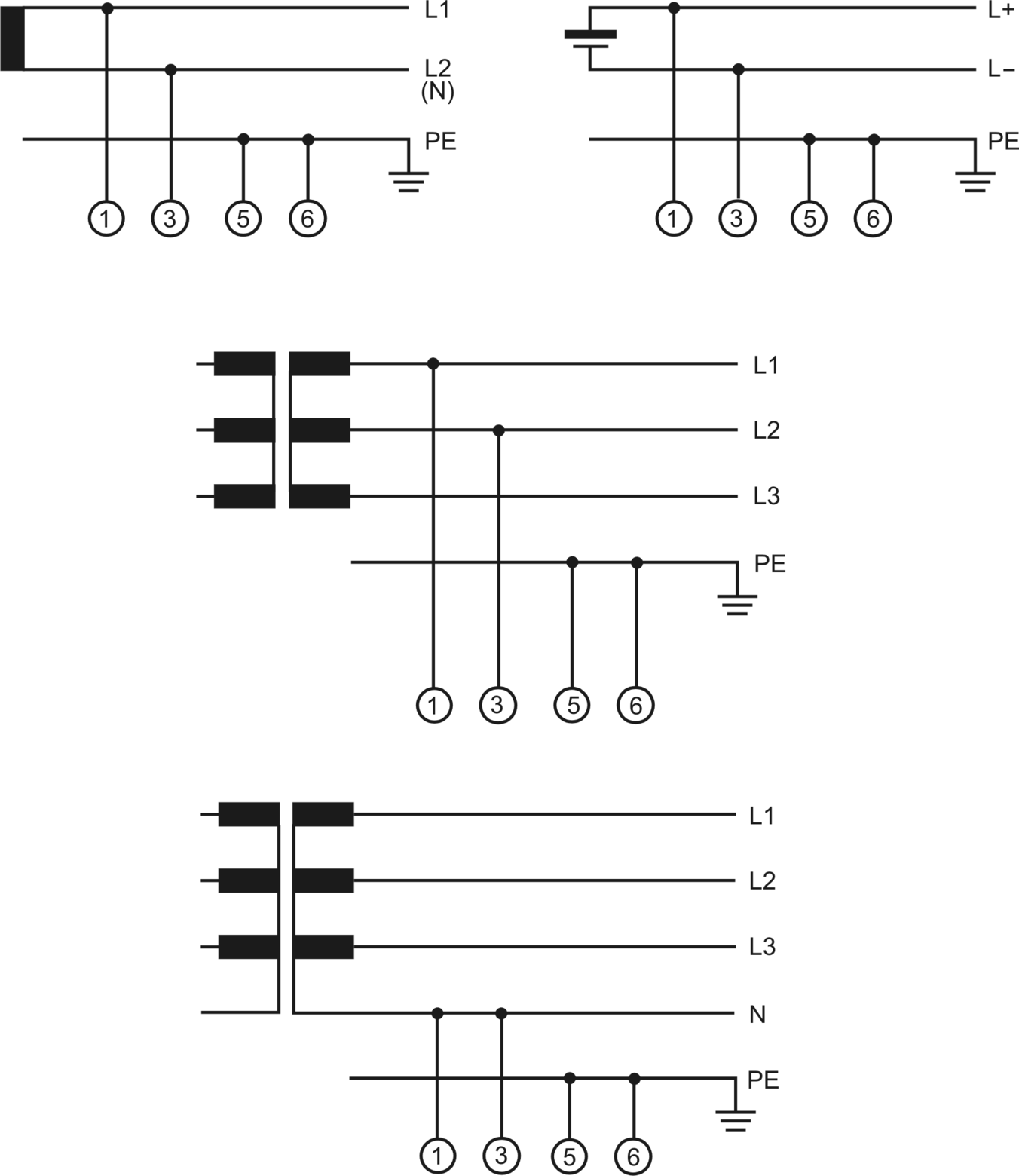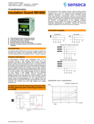
Ungrounded electrical systems need early warning before insulation faults become process risks. The IW1000 monitors insulation resistance in machines and systems with AC, AC/DC and true DC voltage systems up to 690 V, helping operators detect fault conditions in time and maintain safer system operation.
Its time optimized pulse measuring method calculates insulation resistance and leakage capacity after 2-time constants. This shortens response time in well-insulated IT systems with high leakage capacity and supports stable measurement even where frequency converters, phase-angle control, SSR relays or switching power supplies generate DC leakage components.
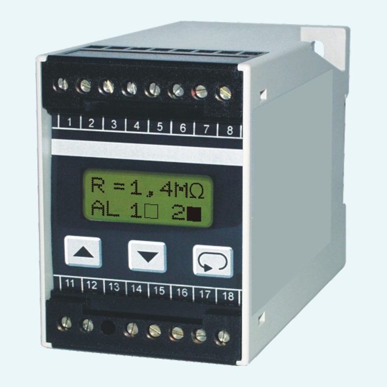
Two programmable SPDT alarm relays, a 0..1 mA analogue output and a backlit two-line LCD make integration straightforward. Automatic and manual self-test functions, acoustic malfunction alarm, DIN rail or wall mounting and versions for railway vehicles or healthcare facilities support reliable use in demanding applications.

he device uses positive and negative measuring pulses to calculate insulation resistance and leakage capacity while eliminating DC voltage shares from leakage capacitances.
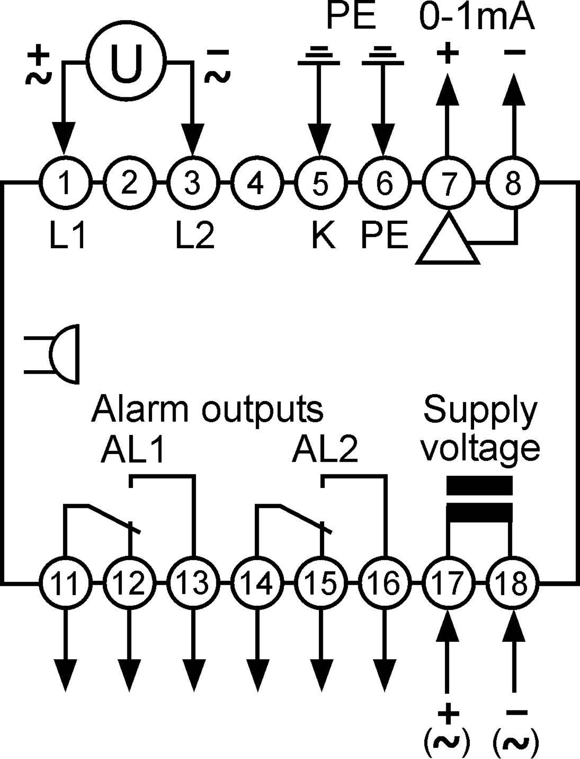
Alarm outputs AL1 and AL2 can be configured for operating or closed circuit principle, hold or hysteresis reset, setpoint, hysteresis and turn-on delay.
The 0..1 mA analogue output represents insulation resistance RF and is intended for connection to an external pointer instrument.
A backlit LCD Dot-Matrix display with two lines of 8 characters shows process values, alarm status and diagnostic messages. Parameters are set via the front keypad.
Automatic and manual self-test functions check device operation. In case of a detected malfunction, the alarm outputs and internal acoustic alarm are activated.
Model variants are available for standard IT systems and for healthcare facilities with reduced measuring voltage and additional terminal monitoring.
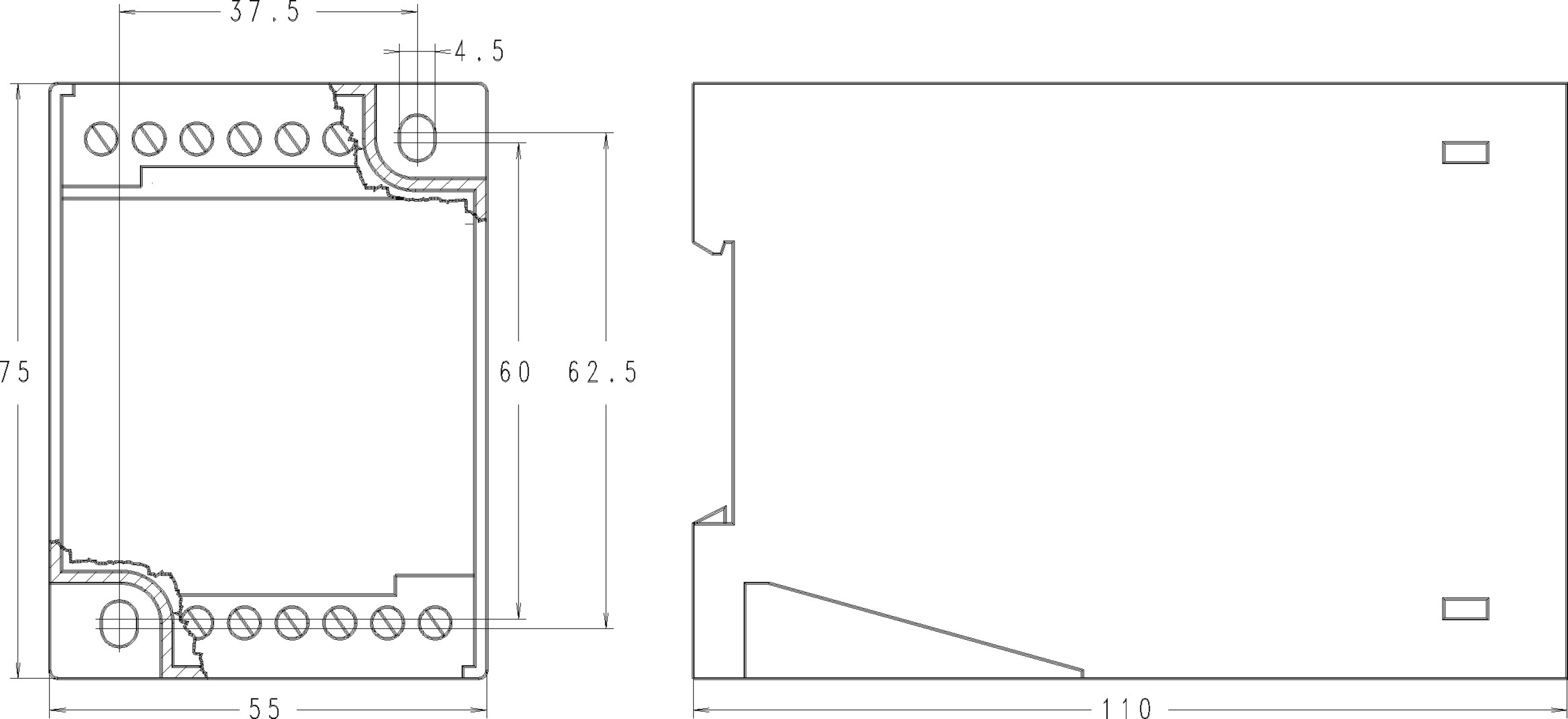
he standard case supports DIN rail TH35 or wall mounting. The housing is Makrolon 8020 UL94V-1 with case IP40 and terminals IP20.
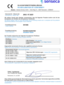
| Voltage range |
For 2 inputs L1 + L2: ±40 V
For 2 inputs L1 + L2 (for each double terminals): ±40 V For 2 inputs L1 + L3, for health care facilities: ±20 kV For 2 inputs L1 + L2 (for each double terminals): ±40 V For 2 inputs L1 + L3, for health care facilities: ±20 kV For 2 inputs L1 + L2 (for each double terminals): ±40 V For 2 inputs L1 + L3, for health care facilities: ±20 kV |
|---|---|
| Current range |
For 2 inputs L1 + L2: ±220 µA
For 2 inputs L1 + L2 (for each double terminals): ±220 µA For 2 inputs L1 + L3, for health care facilities: ±110 µA For 2 inputs L1 + L2 (for each double terminals): ±220 µA For 2 inputs L1 + L3, for health care facilities: ±110 µA For 2 inputs L1 + L2 (for each double terminals): ±220 µA For 2 inputs L1 + L3, for health care facilities: ±110 µA |
| Operating temperature |
For [01] Suitable for railway use: -25...+70 °C
For [01] Suitable for railway use: -25...+70 °C For [01] Suitable for railway use: -25...+70 °C |
|---|
| Type of analog output |
For 2 inputs L1 + L2: 0…1 mA
For 2 inputs L1 + L2 (for each double terminals): 0…1 mA For 2 inputs L1 + L2 (for each double terminals): 0…1 mA For 2 inputs L1 + L2 (for each double terminals): 0…1 mA |
|---|
| Railway |
For [01] Suitable for railway use: NFF16-101 particulary (glow wire testing); NFF16-102 particulary (6.2; 6.4; 6.5)
For [01] Suitable for railway use: NFF16-101 particulary (glow wire testing); NFF16-102 particulary (6.2; 6.4; 6.5) For [01] Suitable for railway use: NFF16-101 particulary (glow wire testing); NFF16-102 particulary (6.2; 6.4; 6.5) |
|---|
| Auxiliary voltage |
For 230 V AC ±10 % 50 ... 60 Hz: 230 V AC
For 24 V DC (16.6 ... 33.6 V DC): 24 V DC For 24 V DC (16.6 ... 33.6 V DC): 24 V DC For 24 V DC (16.6 ... 33.6 V DC): 24 V DC |
|---|---|
| Auxiliary voltage tolerance |
For 230 V AC ±10 % 50 ... 60 Hz: ± 10 %
|