
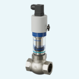
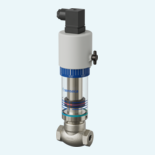


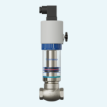
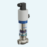

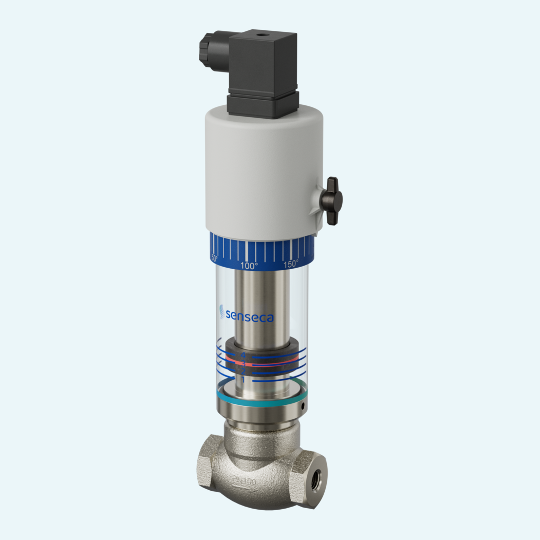
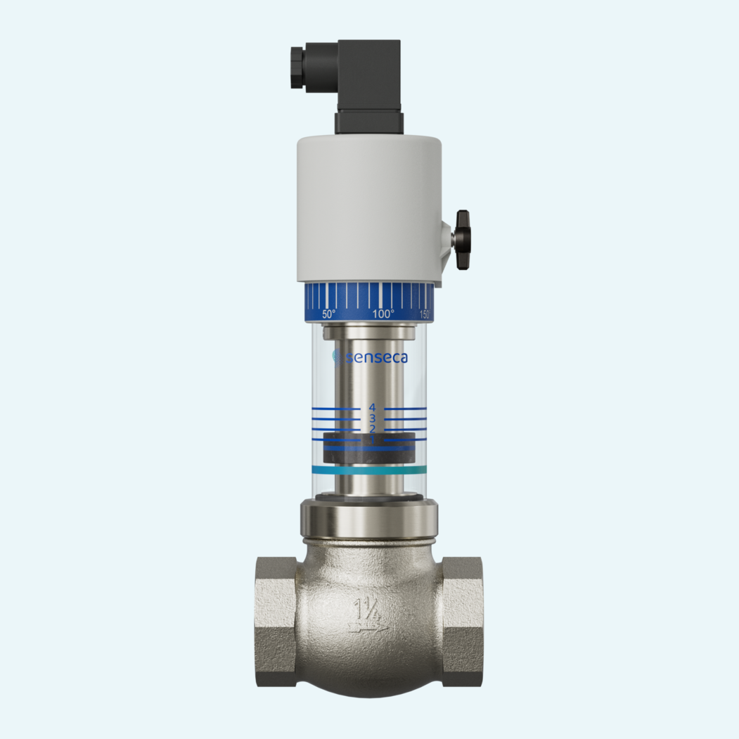
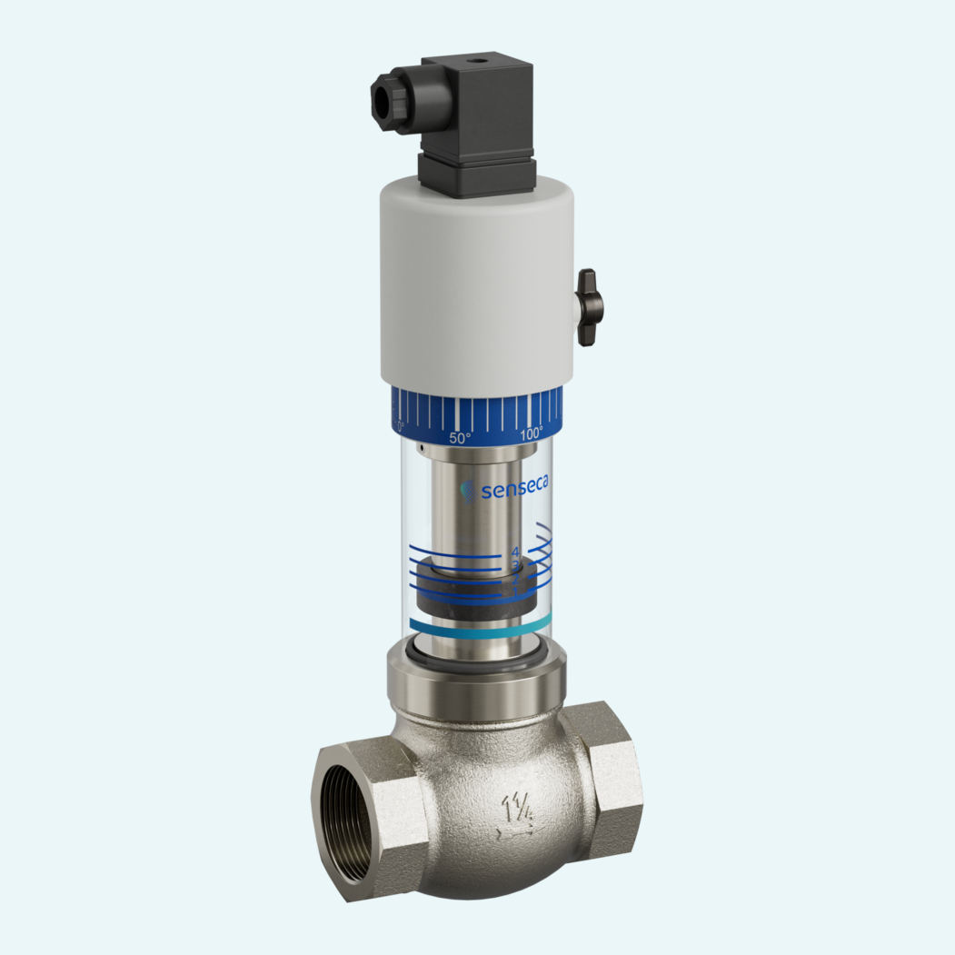
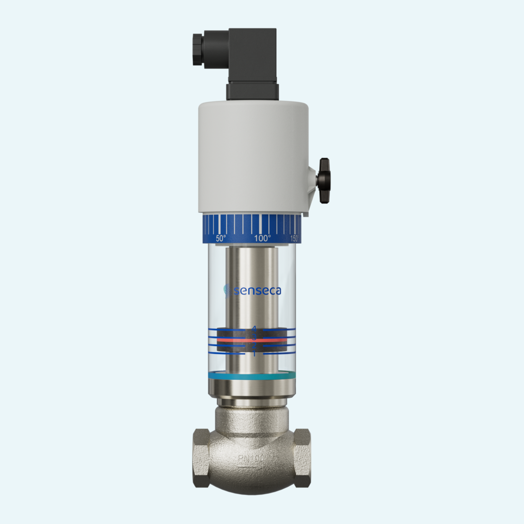
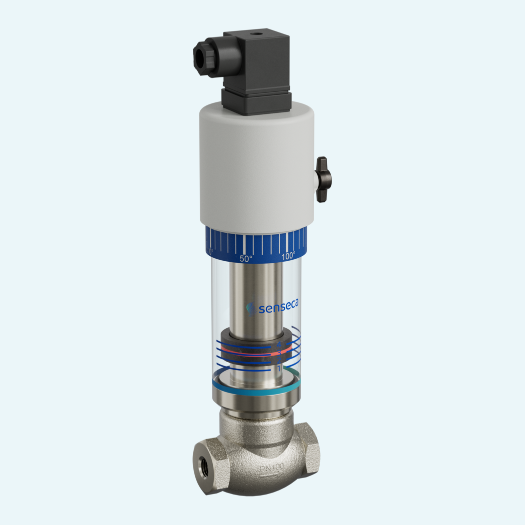
Flow monitoring is easier when the switching function and local indication sit in one compact device. This mechanical flow switch and indicator monitors water lines while showing flow status on site, without pressure- or media-loaded glass parts.
Flow lifts a magnet-equipped piston from the valve seat against spring force. The piston actuates both a hermetically separated Reed switch and a hermetically separated indicator ring. Threaded versions cover DN 8 to DN 80 with G 1/4 to G 3 internal connections, H2O switching ranges from 2-600 l/min and recommended Qmax. values up to 720 l/min. Pressure resistance reaches PN 100 bar for smaller sizes, depending on the connection.
The short installation length supports compact pipework, while precise, stepless switching value adjustment helps set the switching point for the application. Standard mounting uses horizontal flow, supported by 5 x DN straight calming sections in the inlet and outlet. Optional ingress protection (IP65), temperature indication, temperature monitoring and oil switching ranges allow closer adaptation.

Flow lifts a magnet-equipped piston against spring force and actuates a hermetically separated Reed switch.
The piston also actuates a hermetically separated indicator ring. The display can be rotated.
The product family uses G internal threads from G 1/4 to G 3 for nominal widths from DN 8 to DN 80.
Pressure resistance depends on size: PN 100 for G 1/4 to G 1/2, PN 25 for G 3/4 to G 1 and PN 16 for G 1 1/4 to G 3.
The standard connection uses a DIN 43650-A / ISO 4400 plug and a changeover Reed switch.
Horizontal flow is the standard arrangement. Other installation positions are possible, but they affect the switching point or switching range.
The switching point is adjusted by loosening the switch head fixing screw and rotating the switch head.
Options include special connectors, signal lamps, ingress protection (IP65), temperature indication, temperature monitoring, metal cover and stainless steel housing.