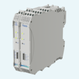
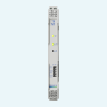

Selected product option for Switch amplifier. All information below applies to the selected product option.

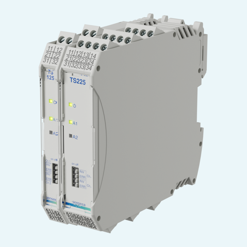
Tight control cabinets still need dependable signal separation. TS125 converts and isolates digital switching signals from passive encoders, switching contacts, NAMUR initiators according to DIN EN 60947-5-6 and passive electronic outputs.
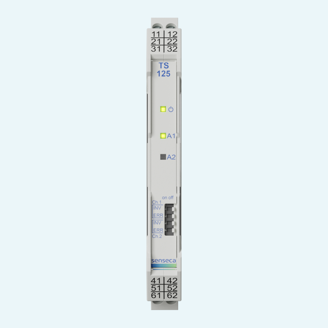
The 12.5 mm DIN rail housing helps save installation space while keeping relay switching clear and configurable. TS125 versions provide relay outputs with closing function and are available as single-channel or dual-channel devices. A single-channel version with a second relay can be used as a parallel relay or fault relay.
For stronger process reliability, optional line monitoring detects wire break below 0.2mA and short circuit above 7mA. DIP switches allow direct or inverted relay behavior, while front LEDs show relay state and fault conditions. Selected versions support intrinsically safe inputs for hazardous-area sensors, and use in SIL2 systems is possible.

The devices accept passive encoders, switching contacts, NAMUR initiators according to DIN EN 60947-5-6 and passive electronic outputs from third-party devices.
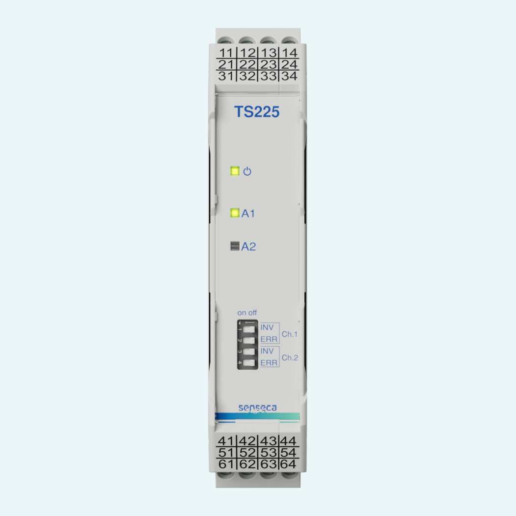
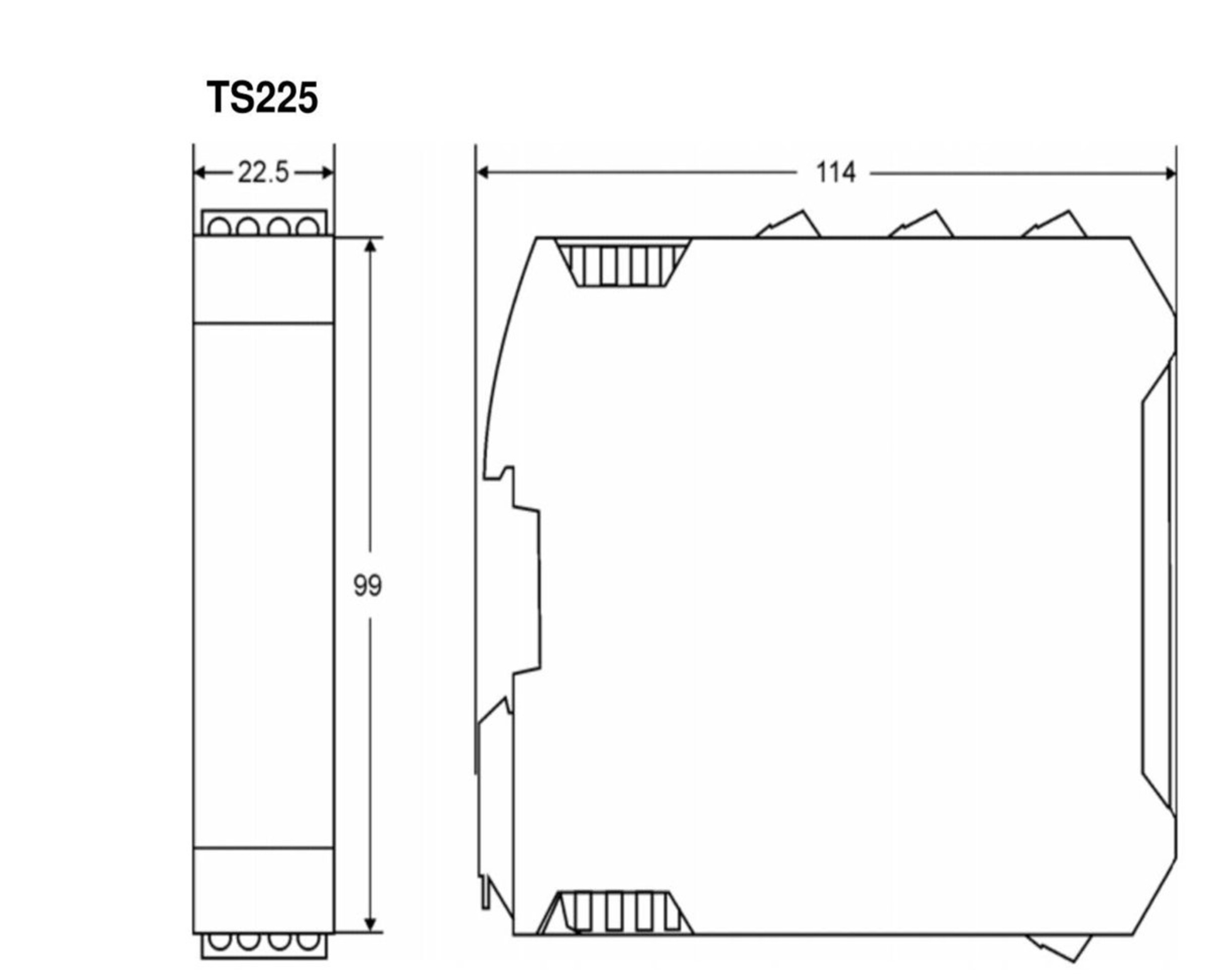
TS125 versions provide relay outputs with closing function. TS225 versions provide relay outputs with changeover function.
The family includes single-channel and dual-channel versions. A single-channel version with a second relay is available for use as a parallel relay or fault relay.
Front DIP switches set direct or inverted output behavior and activate error monitoring for the corresponding input channel.
When monitoring is activated, the device evaluates current thresholds for open circuit and short circuit conditions and indicates errors via the front LEDs.
TS125M and TS225M versions use a wide-range supply. TS125L and TS125LP versions operate with 24V DC +/- 15 %.
TS125LP versions can be supplied via a Power Rail DIN rail adapter, using a bus system in the carrier rail to simplify wiring for multiple devices
Versions with intrinsically safe inputs are available for connection of suitable sensors in hazardous areas, subject to the specified safety-related key values.
| Dimensions |
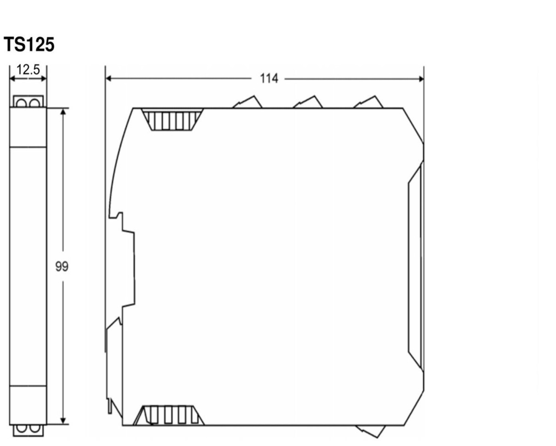
12.5 mm x 99 mm x 114 mm
|
|---|
| Type of switching output |
SPST
|
|---|
| Auxiliary voltage |
For 24 V DC ±15 %: 24 V DC
For 24 V DC ±15 %: 24 V DC For 24 V DC ±15 %: 24 V DC For 24 V DC ±15 %: 24 V DC |
|---|---|
| Auxiliary voltage tolerance |
For 24 V DC ±15 %: ± 15%
For 24 V DC ±15 %: ± 15% For 24 V DC ±15 %: ± 15% For 24 V DC ±15 %: ± 15% |
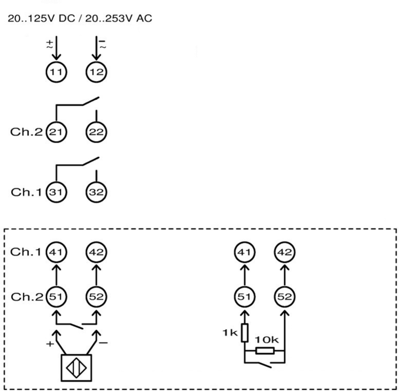
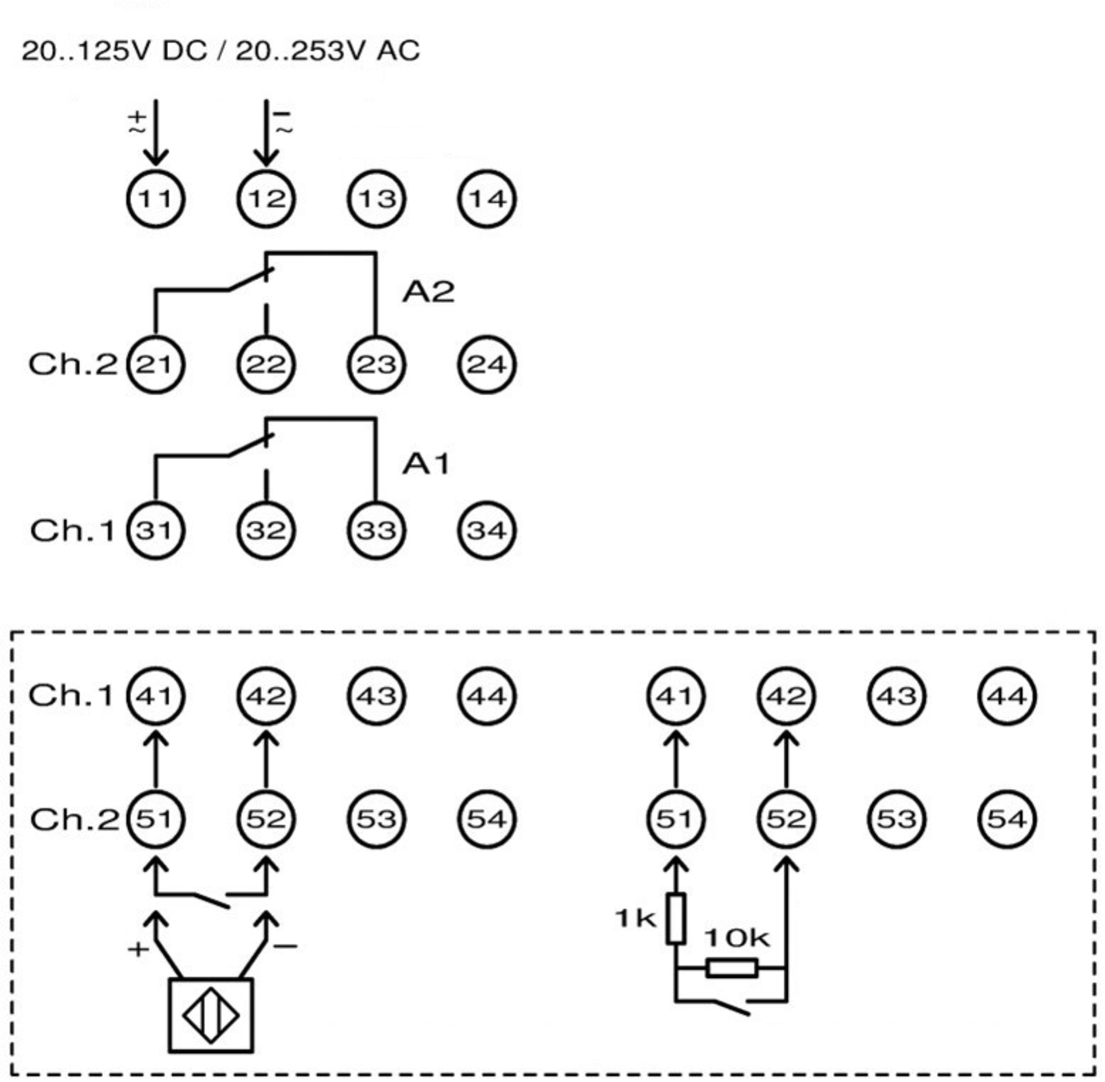
Note: connection diagram showing input wiring of namur and switch contact and separately switch contact with short circuit and circuit break detection (right input drawing)