Resistance and potentiometer signals from hazardous areas need safe separation before they reach the control system. PMT50Ex-2 records intrinsically safe resistance and potentiometer inputs and converts them to galvanically isolated 0/4..20 mA or 0/2..10 V DC output signals.
The device supports resistance measurement from 0..20 kΩ and potentiometer measurement from 1 kΩ to 100 kΩ. Programmable measuring range, 32 base-points for linearization or output characteristic transformation, plus Teach In and simulator functions help adapt non-linear sensor behavior to the process value.
Automatic broken-line detection in the measuring circuit improves fault visibility, with programmable behavior for the analog output at 0 mA, < 3.6 mA or >21.5 mA. ATEX approval TÜV 08 ATEX 554329, graphic LCD and optional relay alarms make it a capable cabinet interface for Ex-related measurement tasks.

PMT50Ex-2 provides intrinsically safe input circuits for resistance and potentiometer signals, with ATEX marking II (1) G [Ex ia] IIC/IIB or II (1) D [Ex iaD].
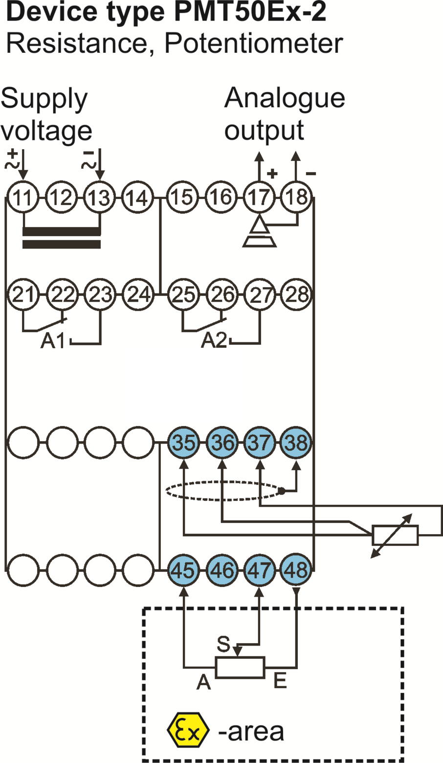
The resistance input covers 0..20 kΩ via terminals 35, 36, 37 and 38. Broken-line monitoring is available in the measuring circuit.
The potentiometer input covers 1 kΩ..100 kΩ via terminals 45, 47 and 48. Basic accuracy is <0.2 %, ±1 Digit
The galvanically isolated analog output provides 0/4..20 mA at burden ≤500 Ω or 0/2..10 V at burden >500 Ω, changing automatically depending on burden
Up to 2 relay SPDT alarm outputs A1 and A2 are available. Alarm contacts can be configured for min. or max. switching behavior
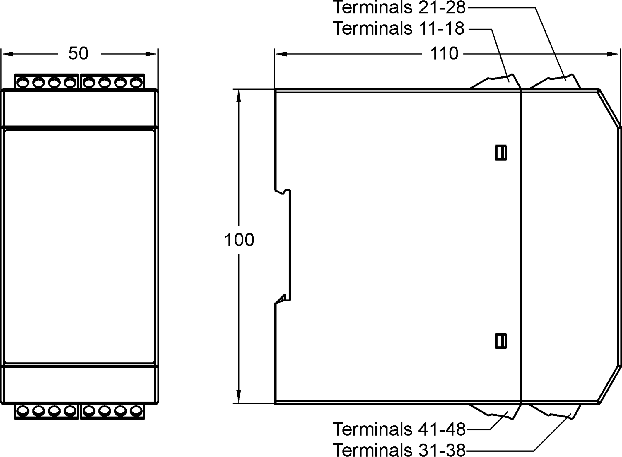
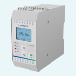
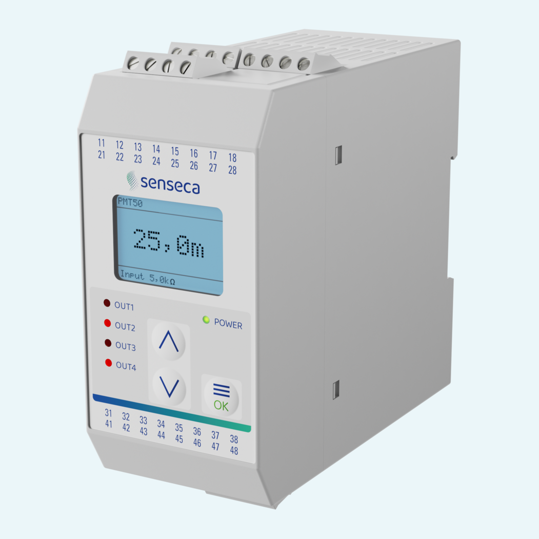
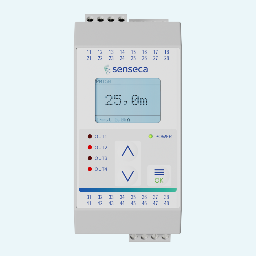
A 128 x 64 pixel graphic LCD with white backlight supports configuration. The PA 6.6 housing mounts on TS35 rails and provides case IP30 with IP20 terminals.