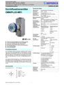
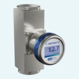

Industrial water circuits need flow measurement that is easy to integrate and strong enough for demanding pressure conditions. This transmitter family measures water from 0.4 ... 60 l/min, with no inlet or outlet runs required for installation in compact machine and plant layouts.
The spring-supported variable area principle provides a clear mechanical basis for the measured value. A magnet-equipped float moves against a spring as the medium flows, while magnetic field sensors detect its position outside the flow chamber. DN 8 ... DN 25 sizes, female threads from G 1/4 to G 1 and \pm5 % full-scale accuracy support reliable flow monitoring across typical industrial water applications.
Integration is handled through one configurable analog output, two switching outputs and IO-Link V1.1. PN 200 pressure resistance, optional PN 500, IP65/IP67 protection and brass or stainless steel versions give the family the flexibility needed for different process and automation environments.

The transmitter uses a spring-supported variable area principle. A magnet-equipped float moves with the medium, and magnetic field sensors detect its position outside the flow chamber.
The product family covers DN 8 ... DN 25 with measuring ranges from 0.4 ... 4 l/min up to 6.0 ... 60 l/min for water.
The devices use female threads from G 1/4 to G 1. Further connection types are available on request according to the source.
The analog output can be configured for current or voltage, including 4 ... 20 mA, 0 ... 20 mA, 0 ... 10 V, 2 ... 10 V, 0 ... 5 V, 1 ... 5 V and 0.5 ... 4.5 V.
Two push-pull transistor outputs can be set as limit switches, frequency outputs, pulse outputs or outputs for the preset counter.
The device supports IO-Link V1.1 with COM2 transmission, SIO mode, block parameterization and data storage.
The graphical 1.2 inch LCD has 128 x 64 pixels and uses white backlighting in normal operation and red backlighting for alarm messages.
The family is available in brass and stainless steel versions, with an optional extended temperature range to +150 °C using distance pieces.