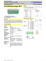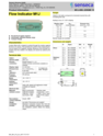
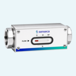
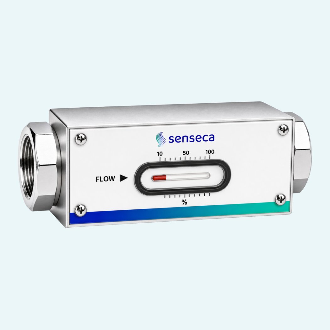
Local flow indication is often needed where wiring adds effort, space is limited or a simple visual check gives operators the confidence they need. This compact mechanical flow indicator works without electrical supply and shows the flow rate directly on a front-facing display.
The magnet-equipped piston is moved by the medium against a spring and actuates the pointer through magnetic coupling. Because the display unit is hermetically separated from the medium, it stays protected from medium contamination. Individually calibrated H2O ranges from 0.4...60 l/min help match the indicator to the application instead of forcing a generic scale.
With DN 8...25 sizes, G 1/4...G 1 female threads and PN 200 pressure resistance, the unit fits demanding process and machine applications. Brass and stainless steel versions cover different material requirements, while oils, gases, aggressive media, special ranges and special scales are available on request.

A magnet-equipped piston moves against spring force as flow increases and transfers this movement to the pointer through magnetic coupling.
The J version provides a frontal measuring display with a 10...100 % indication scale for the selected calibrated range.
The family includes nominal sizes DN 8, DN 10, DN 15, DN 20 and DN 25 with female threaded connections from G 1/4 to G 1.
Brass versions use nickel-plated CW614N and NBR in contact with the medium. Stainless steel versions use 1.4571, 1.4404 and FKM.
Standard calibration is for horizontal flow from the left. Other mounting positions are possible, but the installation position affects the indication range.
The indicator is specified for medium temperatures from -20...+120 °C and ambient temperatures from -20...+70 °C.
Available options include special ranges, special scaling, a 0...120 °C temperature indication and a reinforced piston.