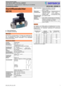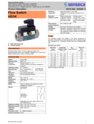
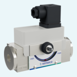
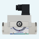
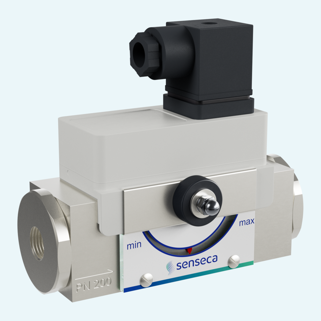
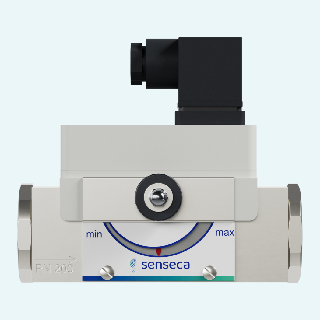
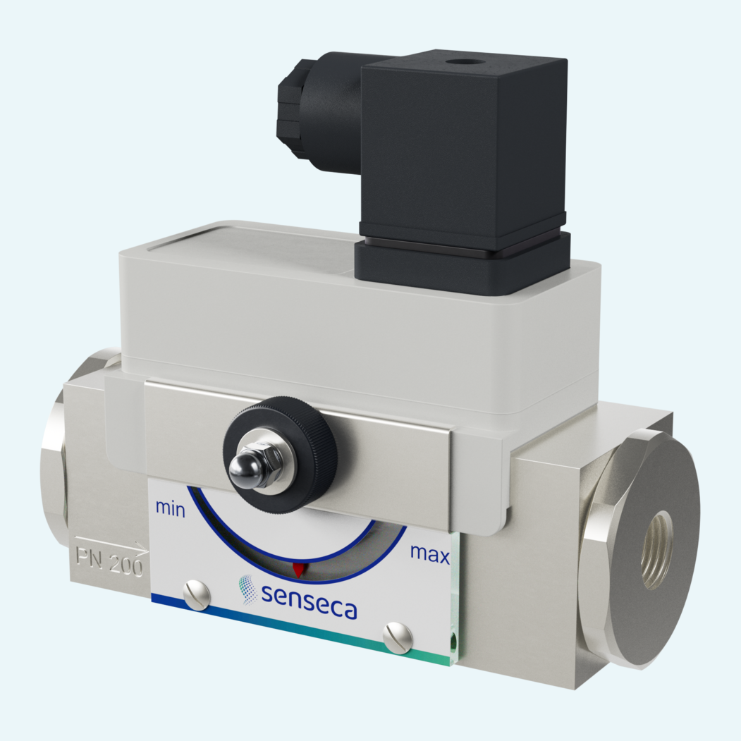
In process lines where flow has to be monitored without complex electronics, a mechanical switching principle keeps operation clear and robust. The unit monitors liquid media such as water and oil and covers H2O switching ranges from 0.1...80 l/min across DN 8...25 sizes.
A spring-supported piston actuates a reed switch magnetically, giving users a compact flow monitoring point with up to 5 W / VA switching capacity. Brass and stainless steel versions support different media requirements, while PN 200 pressure resistance and optional PN 500 extend use in demanding installations.
Commissioning stays practical on site. The switch head can be adjusted by pinion setting and fixed with an SW 8 screw, with optional side or front mechanical indication and DIN 43650-A / ISO 4400 electrical connection rated to ingress protection (IP65).

The standard switching element is a reed switch. Changeover contacts are specified, with optional contact versions listed for normally open operation and higher AC/DC loads. ATEX switching elements are available optionally.
Versions are available without indication, with side measurement indication O1 or O, or with front measurement indication Z1. Optional scale division in l/min can be specified.
Standard installation uses horizontal flow from the left. Other mounting positions are possible, but the position affects the switching point or switching range.
Straight calming sections of 5 x DN in the inlet and outlet are recommended. Filters are specified for dirty media, with magnetic filters for ferritic particles.
The standard medium temperature range is -20...+120 °C. Options include medium temperature up to +150 °C, temperature monitoring and 0...120 °C temperature indication.
The standard electrical connection uses a DIN 43650-A / ISO 4400 plug. A 4-pin M12x1 round connector is available as an option.