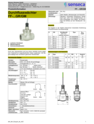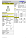
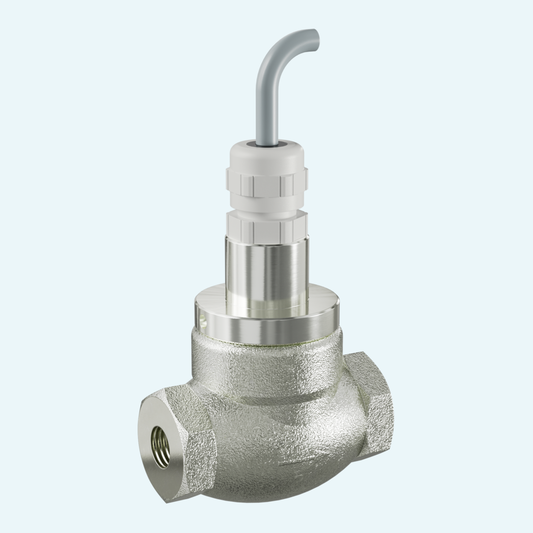
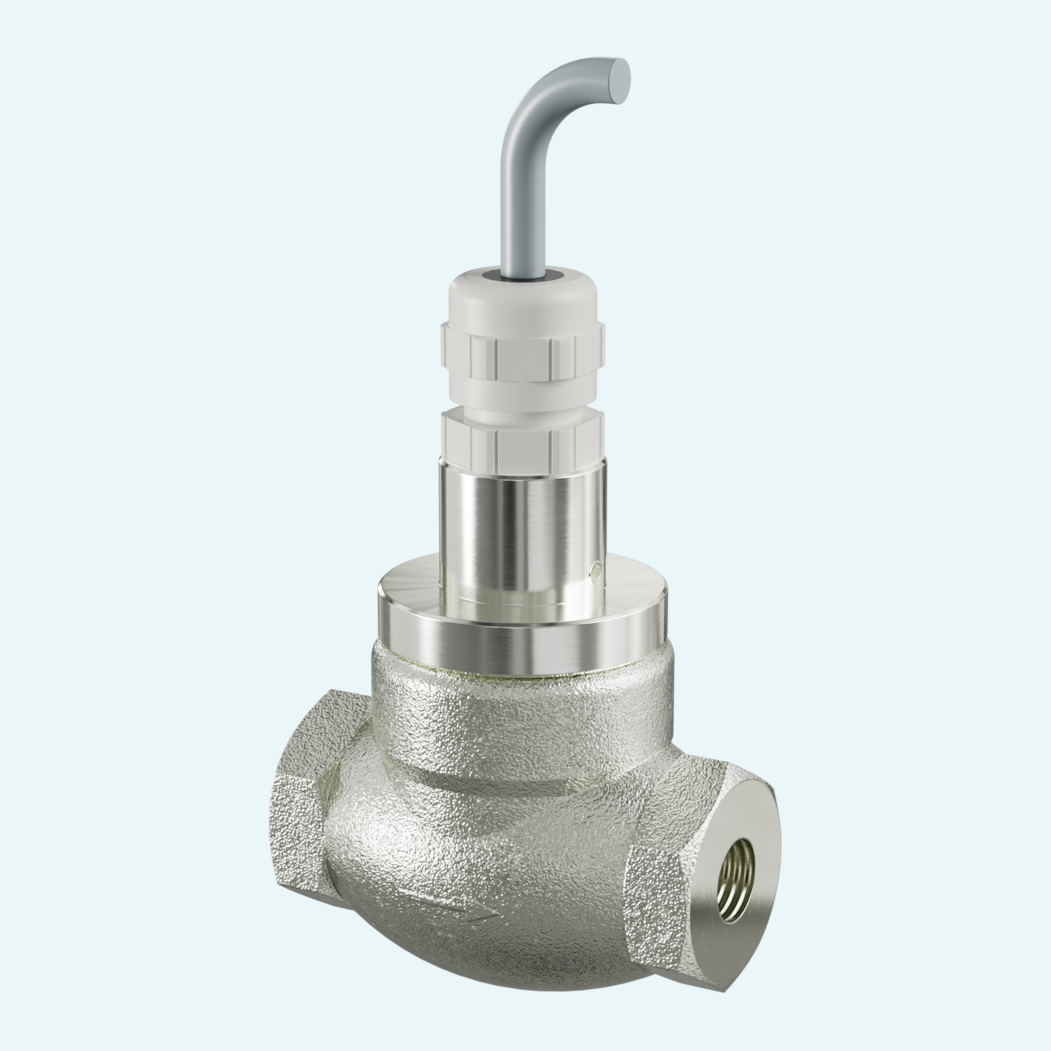
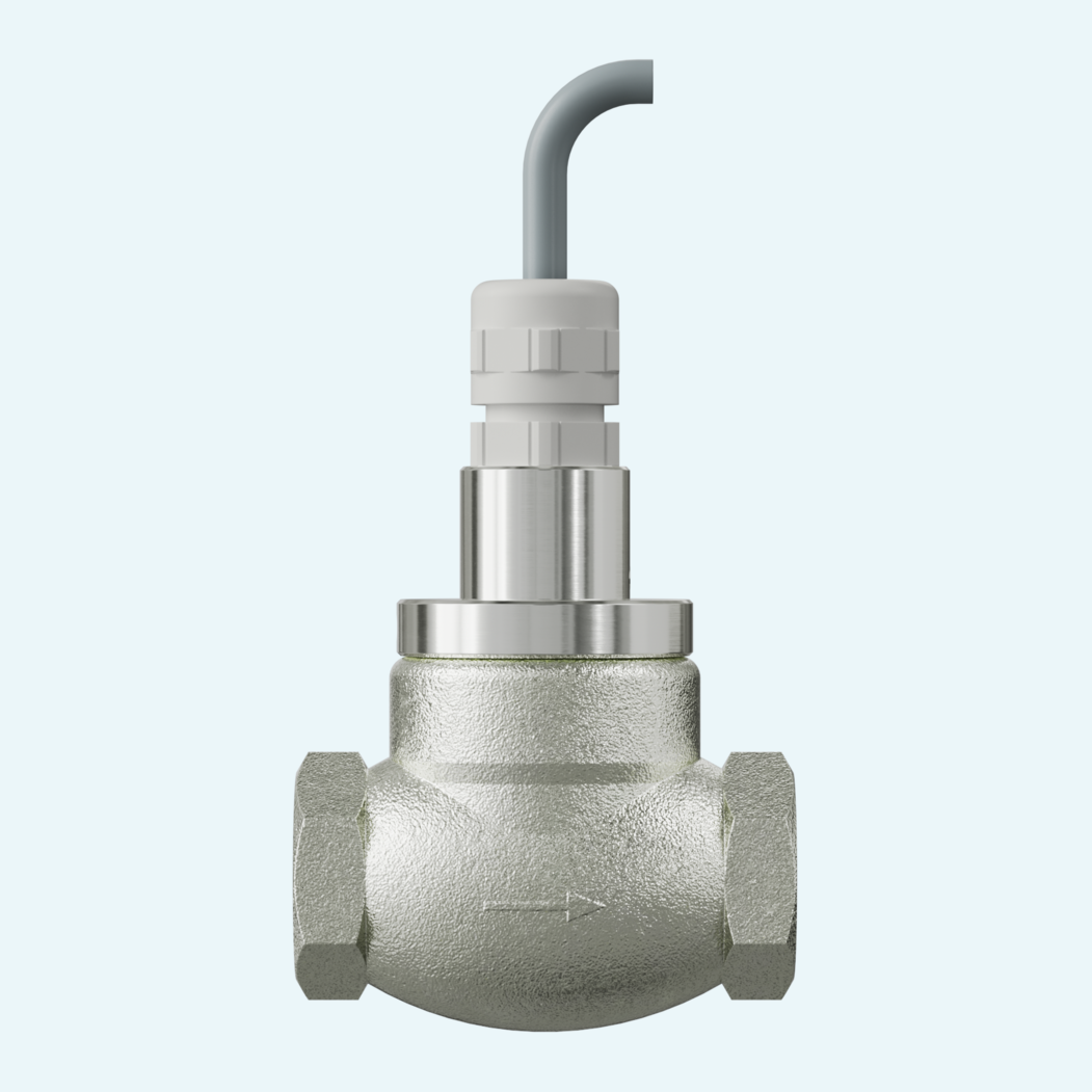
Stable flow monitoring starts with a defined switching point. This family lets you select the H₂O setpoint for the line size, from 0.4...90 l/min across DN 8...40, with a tolerance of ±3 % from the setpoint and a minimum of ±0.3 l/min.
The mechanical piston principle gives you a clear, repeatable switching action for water applications. Flow lifts a magnet-equipped piston against spring force, and the magnet actuates a hermetically separated reed switch. The design is described as dirt-insensitive; for contaminated media, a filter is recommended, or a magnetic filter where ferritic particles are present.
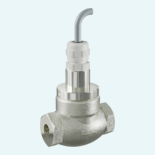
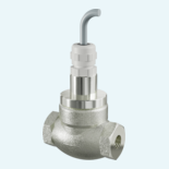
With G 1/4...G 1 1/2 female-thread connections, IP65 ingress protection and pressure ratings from PN 16 to PN 200 depending on size, the flow switch fits directly into demanding process and machine environments. A normally open contact is standard, with a normally closed version available on request.

The volumetric flow lifts a magnet-equipped piston from the valve seat against spring force. The magnet actuates a hermetically separated reed switch.
The family is specified for water; oil and gas adjustment is available on request. Wetted materials include nickel-plated Rg 5, 1.4310, nickel-plated CW614N, NBR and hard ferrite.
The switch uses a 1.8 m cable and protection class 1 with protective conductor connection.
Horizontal inflow is standard. Other mounting positions are possible, but the position influences the switching point or range; downward switch head position is not recommended.
Ordering defines nominal diameter, female-thread connection, connection material, H₂O switching point and contact diagram.