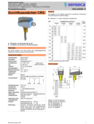
Clear flow supervision matters when pumps, circuits or process lines need a defined switching point. For water applications in DN 25...200 pipework, the device monitors flow with selectable H2O switching ranges from 0.2...165.7 m3/h and a recommended Qmax. up to 240 m3/h.
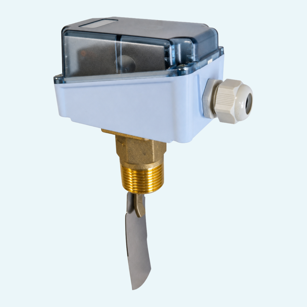
The metal-bellows-supported paddle actuates a changeover microswitch, giving a straightforward switching function for industrial control tasks. Brass and stainless steel versions are available, with wetted materials CW614N, 1.4571 and tombak in the brass version, or 1.4571 in the stainless steel version. It is also suitable for media containing ferritic particles.
Site integration stays practical: ingress protection (IP65) supports industrial environments, and the unit handles media temperatures from -20...+120 °C at PN 11. Horizontal flow is standard; other mounting positions are possible, with an influence on the switching point.

The device works with a metal-bellows-supported paddle that actuates a microswitch as flow changes.
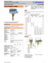
The switching value is set with an adjustment screw after removing the cover, then the cover is secured again.
Horizontal flow with the switching unit not facing down is the standard recommendation. Other installation positions are possible and influence the switching point or range.
The changeover contact uses white, red and blue leads. A load must be connected in series when wiring the switch.
The installation notes specify a straight calming section of 10 x DN upstream and downstream. A filter is recommended for contaminated media.
The order key includes an optional R version for reduced switching ranges. Oil switching ranges and special flow rates are available on request.