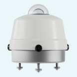
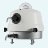
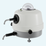
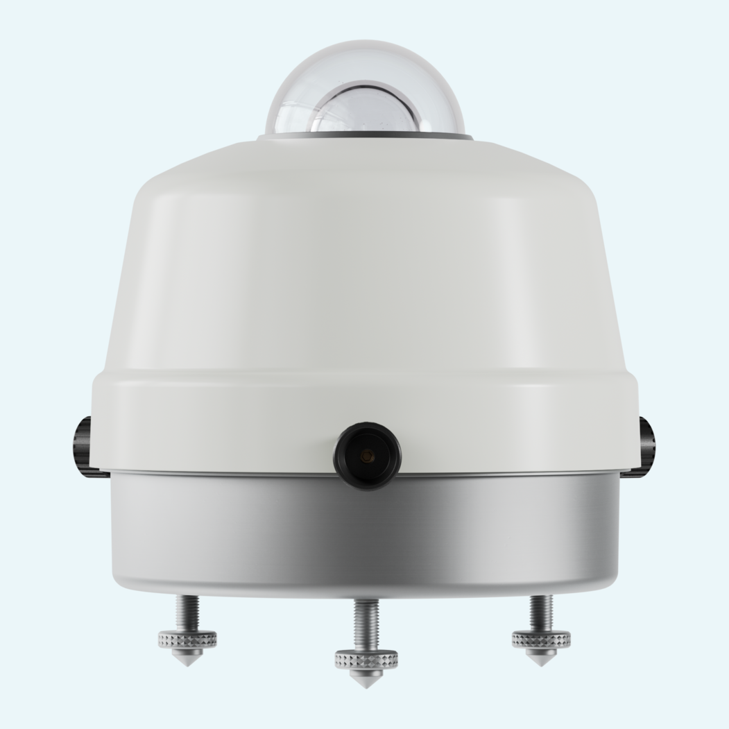
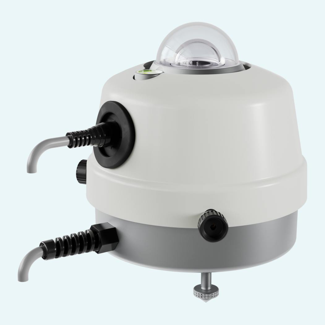
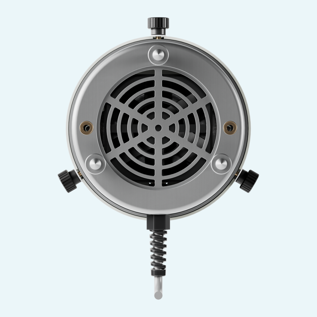
Stable solar radiation data depends on keeping the pyranometer dome clear and the sensor temperature uniform. VUP12 ventilates compatible pyranometers to reduce type 'A' offset caused by dome cooling, while helping prevent dew and frost on the optical parts during continuous outdoor operation.
For colder climates, VUP12 adds heating that can be matched to site conditions. Two independent heating circuits of equal power can be activated individually or together, helping prevent snow and ice formation on the dome. Ventilation is intended to run continuously, while heating activation depends on ambient temperature and local humidity conditions.
Designed for outdoor use in any weather, the unit operates from -40...+70 °C at 0...100 %RH and connects via an 8-pole M12 connector. It is suitable for LPS02... and LPS10... series pyranometers and supports solar radiation measurements aligned with ISO/TR 9901, IEC 61724-1 and the 'BSRN operations manual'.


The fan runs on 12 Vdc \pm 10% / 1.6 W and is normally always in operation to keep the pyranometer temperature uniform and reduce dust settling.
Two separate heating circuits run on 12 Vdc ± 10%, rated 6 W each, and can be activated independently.
The unit uses an 8-pole M12 connector. Fan polarity must be respected, while heating supply has no polarity.
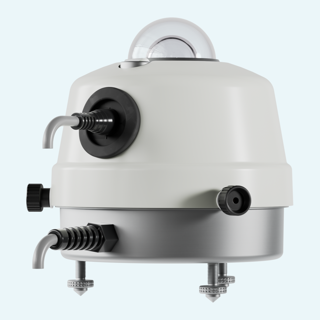
The pyranometer mounts on an internal plate, and the sensor cable routes through a membrane cable gland on the cover.
Height-adjustable feet support levelling. Two M6 holes on the bottom allow fixing to a support plate, with at least 2 cm clearance underneath for airflow.
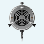
Lower grids should be kept clean to ensure airflow. The upper shell can be removed for thorough cleaning.
| Operating temperature |
-40...+70 °C
|
|---|---|
| Degree of protection case |
IP54
|
| Relative humidity, ambient |
0...100 %RH
|
| Height above sea level. |
3000 m
|
| Weight |
600 g
|
|---|
| Conformity |
IEC 61724-1, ISO/TR 9901, BSRN
|
|---|
| Electrical connection type |
M12
|
|---|
| Auxiliary voltage |
12 V DC
|
|---|---|
| Power consumption |
12 V DC, ± 10% / 1.6 W
|
| Auxiliary voltage tolerance |
± 10 %
|
| Additional power consumption with Direction Finder |
6 W
|