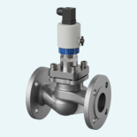

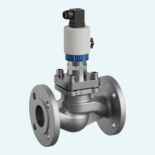
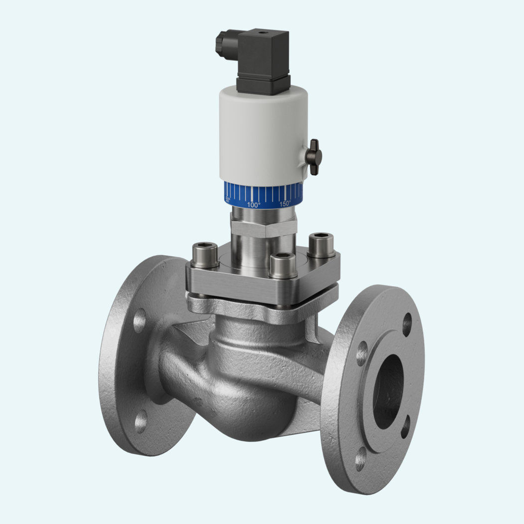
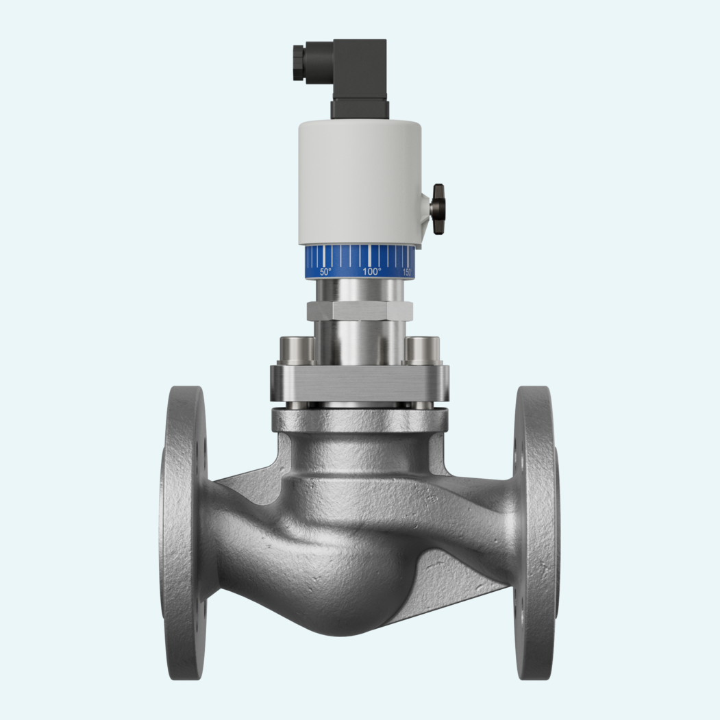
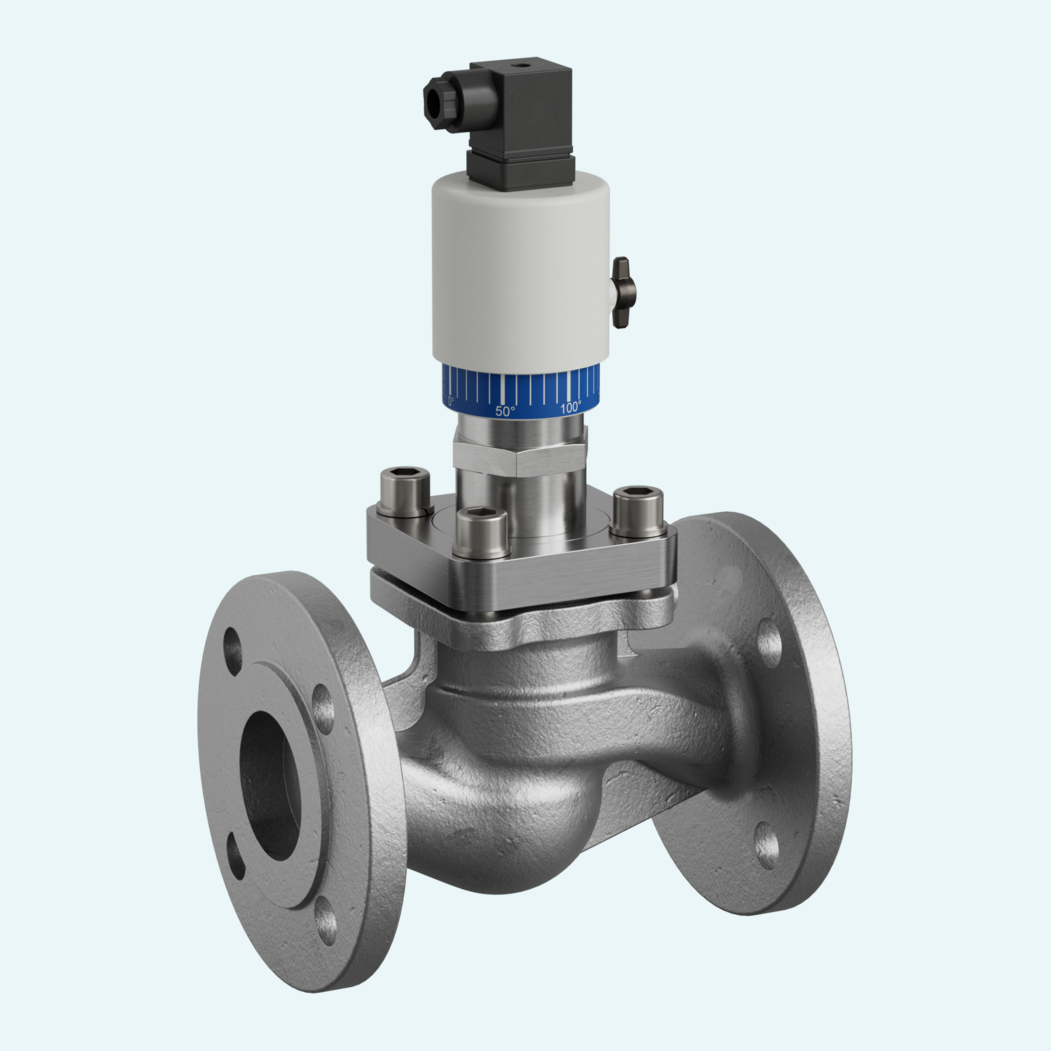
Flow monitoring in industrial liquid lines depends on a clear switching point and a housing that fits the process. This mechanical flow switch combines contactless actuation of an adjustable Reed contact with accurate switching value setting via a 180° scale and setting diagram.
The cast steel flange design covers DN 15 to DN 150 pipe sizes and H2O switching ranges from 2-950 l/min. Recommended Qmax. values extend up to 2000 l/min, while PN 40 pressure resistance, \pm5 % full-scale tolerance and media temperatures from -20..+120 °C support dependable use with water and oils.
Standard installation is based on horizontal flow, with the switching head not recommended in a downward position. Straight calming sections of 5 x DN in the inlet and outlet support stable operation. Options such as ingress protection (IP65), temperature indication, temperature monitoring, a metal cover and oil switching ranges allow the configuration to be matched more closely to the application.

The device monitors flow in liquid media through contactless actuation of an adjustable reed contact.
The construction uses cast steel GSC 25 as the connection material, with wetted materials including 1.4310, CW614N, POM, NBR, Klingerit and hard ferrite.
The flange version follows DIN 3202, series F1 length, DIN 2545 PN 40 flange and DIN 2526 Form C sealing face.
The standard connection uses a DIN 43650-A / ISO 4400 plug and a changeover Reed switch.
Horizontal flow is the standard arrangement. Other installation positions are possible, but they affect the switching point or switching range.
The switching point is adjusted by loosening the switch head fixing screw and rotating the switch head.
Straight calming sections of 5 x DN are required in the inlet and outlet. Filters are recommended for contaminated media.
Options include signal lamp, temperature indication, temperature monitoring, ingress protection (IP65), metal cover and higher media temperature resistance.