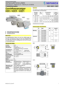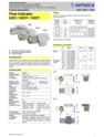
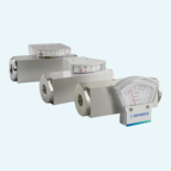
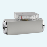
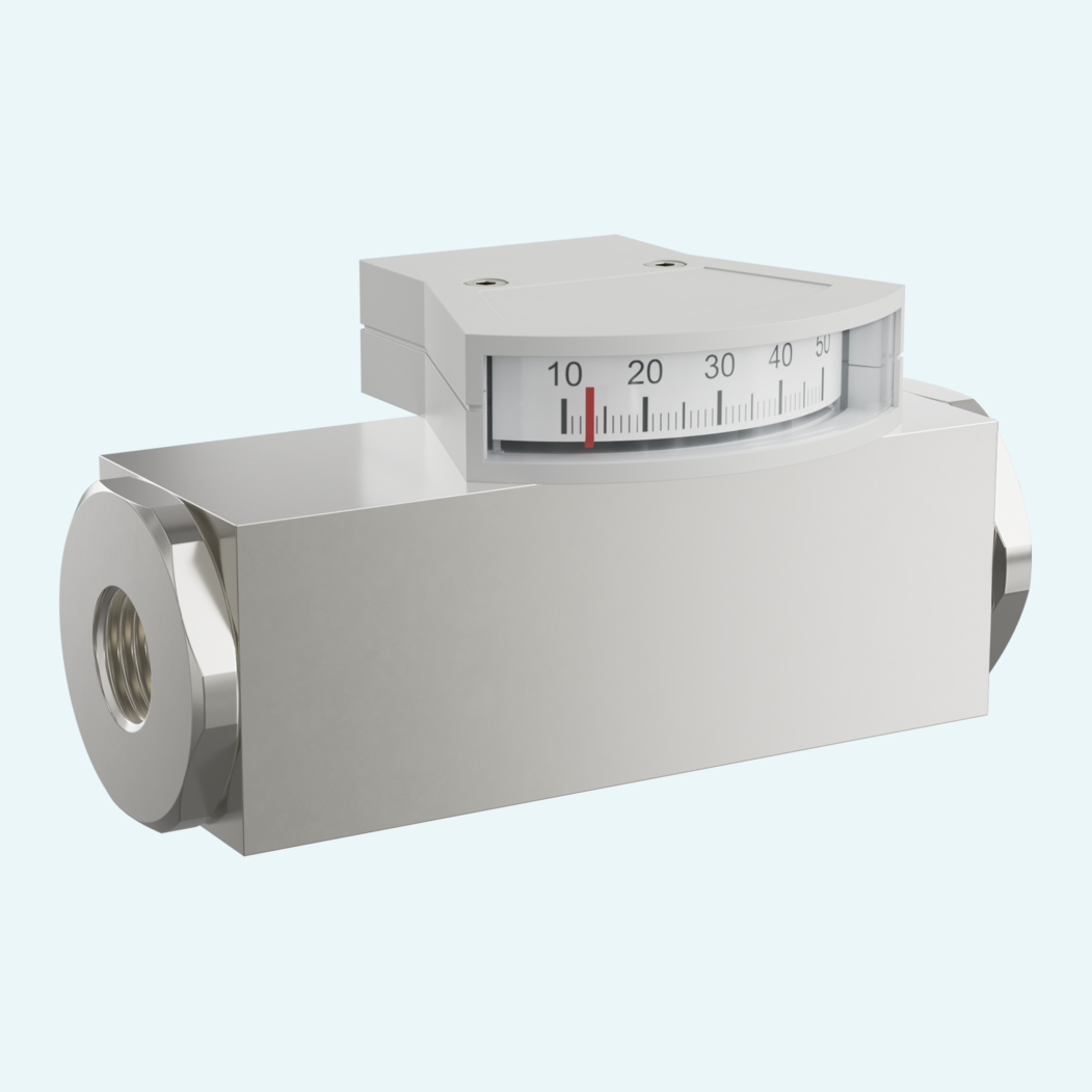
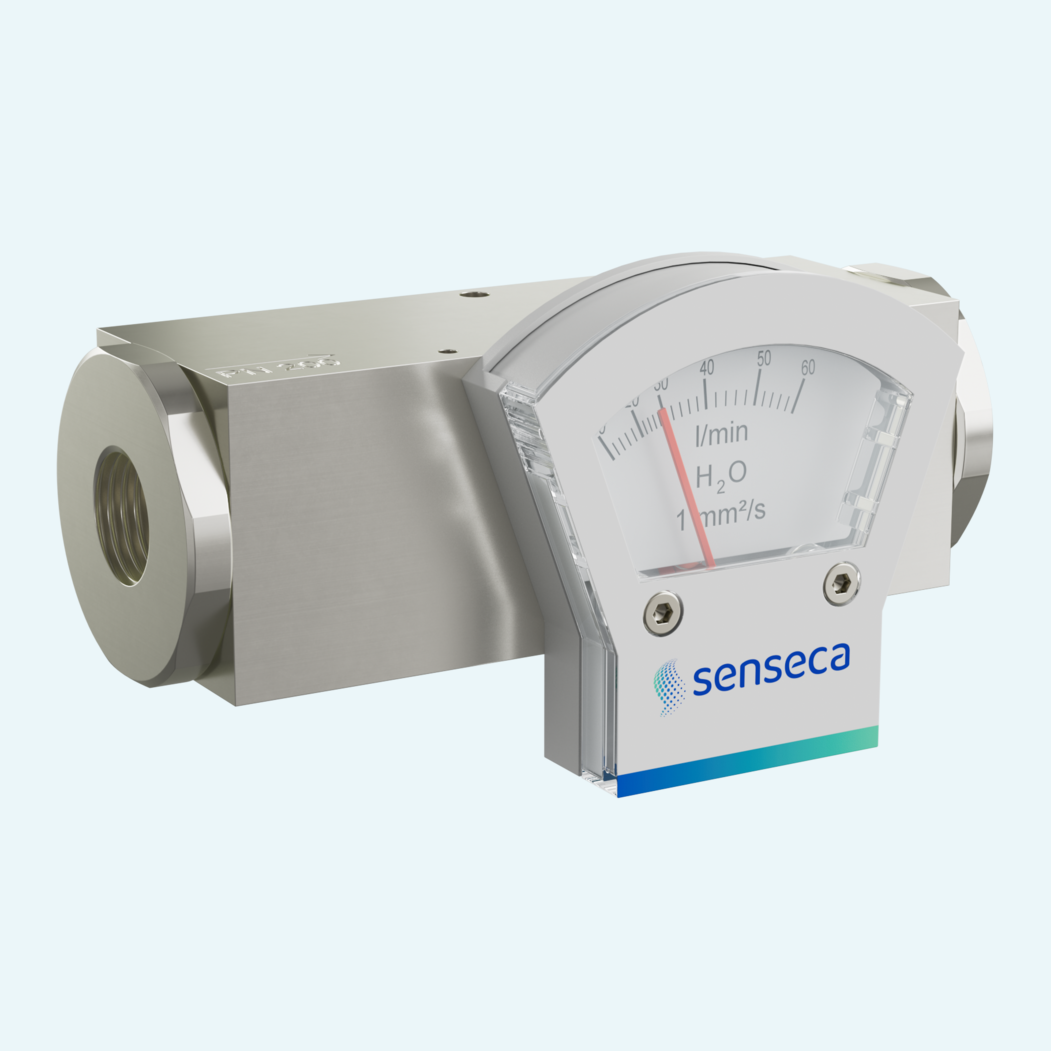
Oil flow needs to stay visible even where power, wiring or electronic displays are not part of the installation. This compact mechanical flow indicator shows the flow directly on site without an electrical supply, helping operators check flow conditions at a glance in hydraulic and lubrication-related oil circuits.
The indication is individually calibrated and available for oil ranges from 0.5...65 l/min. A magnet-equipped piston moves against a spring and transfers the position to the pointer through magnetic coupling, while the indicator unit remains hermetically separated from the medium. That keeps the display area protected from contamination by the oil.
With DN 8...25 internal threads, brass or stainless steel wetted materials and PN 200 pressure resistance, the family covers a practical range of industrial oil applications. PN 500, special ranges, special scaling, a 0...120 °C temperature display and a reinforced piston are available as options.

A magnet-equipped piston is moved by the medium against a spring and transfers its position to the pointer through magnetic coupling.
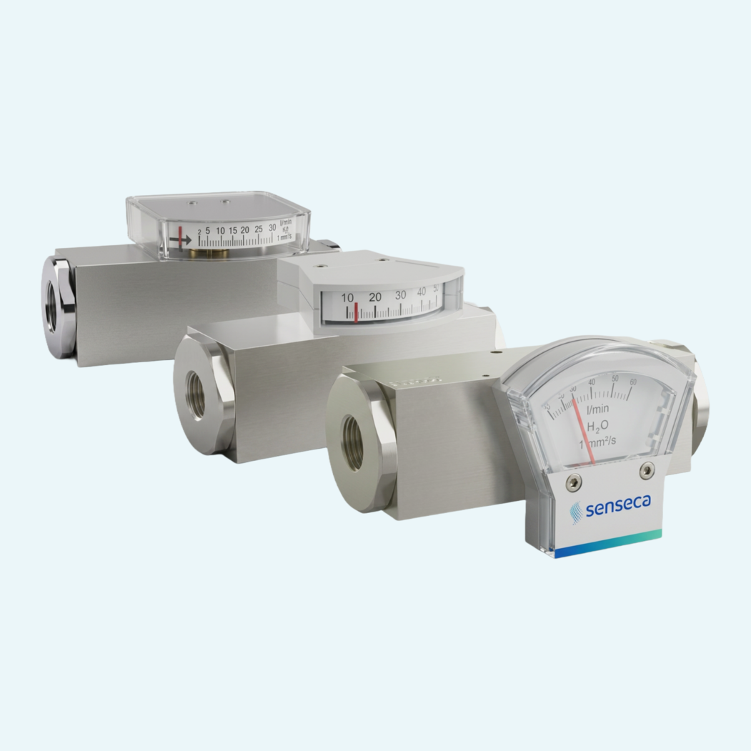
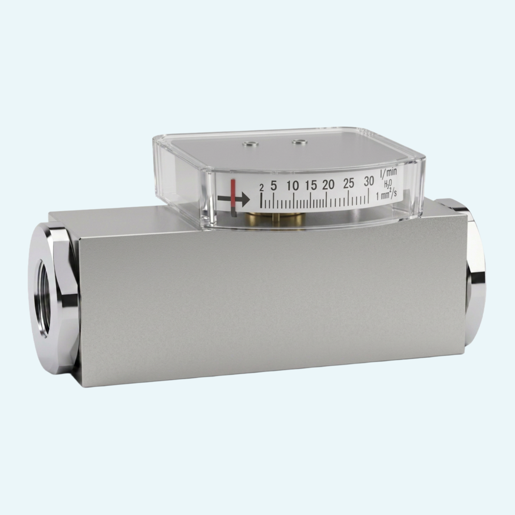
The family includes side measuring display versions O and O1, plus a front measuring display version Z1.
Nominal sizes cover DN 8...25 with internal threads from G 1/4 to G 1. Further connection types are available on request.
Wetted parts are available in brass with nickel-plated CW614N components or in stainless steel with 1.4571 and 1.4404 components.
The standard installation is horizontal flow from the left. Other mounting positions are possible and affect the indication range.
A straight calming section of 5 x DN is specified at the inlet and outlet. Filters are recommended for contaminated media.
Special ranges, special scaling, PN 500 pressure rating, 0...120 °C temperature indication and a reinforced piston are listed as options.