In water-carrying pipework, a defined switching point helps operators react before flow conditions move outside the desired range. This flow switch monitors water flow in nominal pipe sizes from DN 25 to DN 200 and is also suitable for media containing ferritic particles.
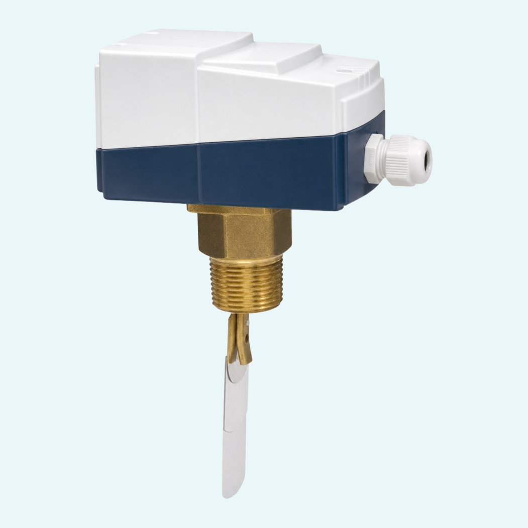
The metal-bellows-supported paddle actuates a microswitch as flow changes, giving the user a clear switching function for process monitoring tasks. Adjustable switching ranges from 0.19 to 165.7 m3/h H2O, with recommended Qmax values up to 240 m3/h, allow the device to cover a wide range of pipe sizes with one product family.
Brass and stainless steel versions support different medium contact requirements, with wetted materials including CW614N, 1.4571 and Tombak in the brass version, and 1.4571 in the stainless steel version. Ingress protection (IP65), a protective conductor connection and 250 V AC, 15 A switching data make the CRE suitable for robust industrial installation.

The device uses a metal-bellows-supported paddle that actuates a microswitch when the flow changes.
The switch uses changeover contact wiring with white, red and blue conductors and electrical data of 250 V AC and 15 A for ohmic loads.
Standard installation uses horizontal flow. Other installation positions are possible, but the position affects the switching value or switching range.
Electrical connection is made via an M16x1.5 cable gland with protective conductor connection.
The installation notes specify straight calming sections of 10 x DN upstream and downstream of the device.
The order code defines connection size, connection material, side cable gland and optional reduced switching range.